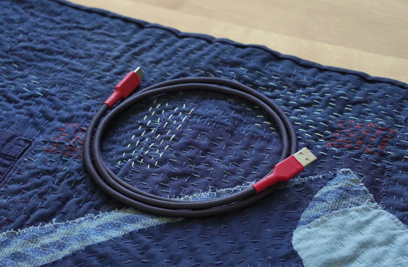
Now that my GMK Indigo-inspired desk mat is done, it’s time to make the second component (of three) of the Indigo-themed desk setup: the USB cable.
Side Note: I initially wanted to write this post simply to take you along while I put a cable together. However, if you were interested in making your own, I think you could take this post as somewhat instructional, and I have tried to explain and document my steps with that possibility in mind. Though I must add that I am a hobbyist and my skills are reflective of that.
Now, before we start, we’ll need some supplies!
These are what I would consider the essential cable parts required:
- 28 AWG 4-core shielded wire
- Paracord 550 lb
- USB-A 2.0 connector + housing/cover
- USB-C 2.0 connector + housing/cover
- 3:1 Heat shrink tubing (sizes: 1/2″ + 3/8″)
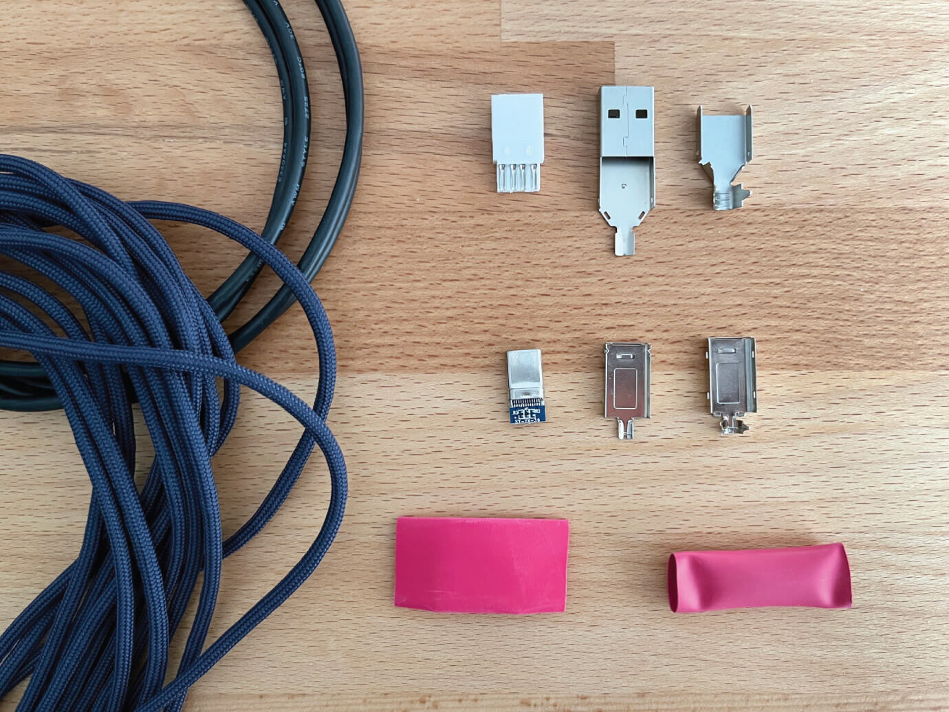
For this particular cable, I’m using FS Navy Blue paracord and red heat shrink. I’ve purchased cable parts from different sources over the past couple of years and will leave links to them at the end of the post.
I usually add PET braided sleeving (e.g. Techflex) on top of the paracord as an extra protective layer, but have chosen to forego it for this particular cable assembly. The paracord I’m using for Indigo is a great colour match to the mat and keycaps and I would like it to show through as is.
I will also be attaching a 5-pin GX-16 aviator connector, but I’ll cover that process in a follow-up post. Aviator and other similar detachable connectors, when used in mechanical keyboard cables, are usually added for aesthetic purposes, but I also like that they weigh down my cables and keep them in place on my desk.
Both of these items are optional, come in many colours and styles, and can be combined to make a cable more appealing.
With the cable components covered, we’ll also need some basic tools to assemble it, pictured below.
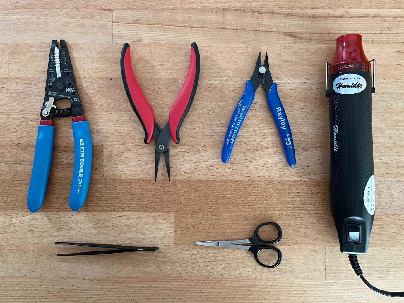
Bottom: Fine-point tweezers and small scissors.
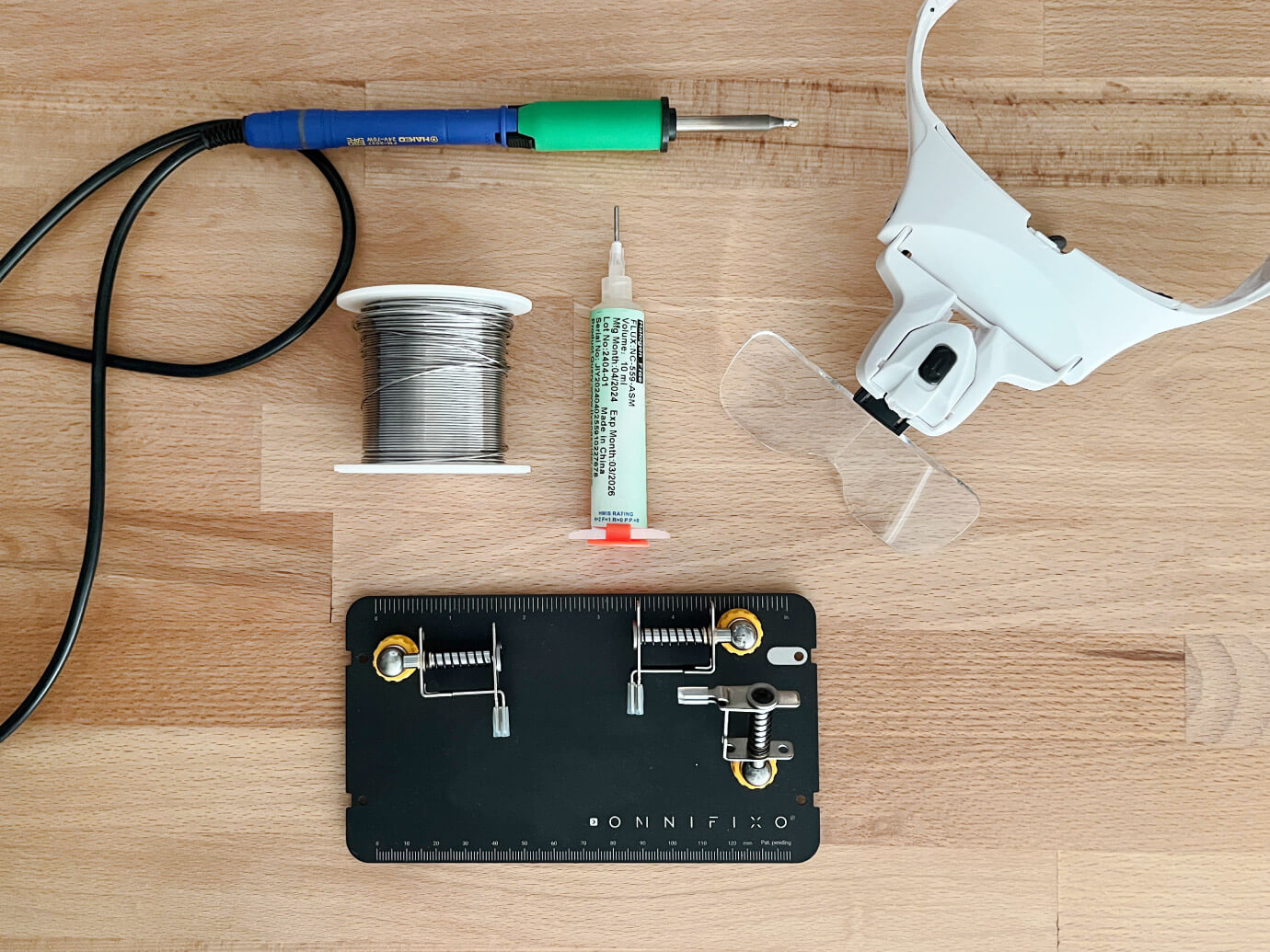
Bottom: Omnifixo helping hands station.
Now that we have everything we need, here are the steps I took to assemble this mechanical keyboard USB cable.
Your cable length can be as long or short as you’d like, whatever suits your needs, but I think the average length is around 5 ft. For my setup and the distance between my keyboard and my computer’s connection ports, 4.5 ft. works well. So, to start, cut your desired length of cable wire, and cut your paracord about 4″–6″ longer.
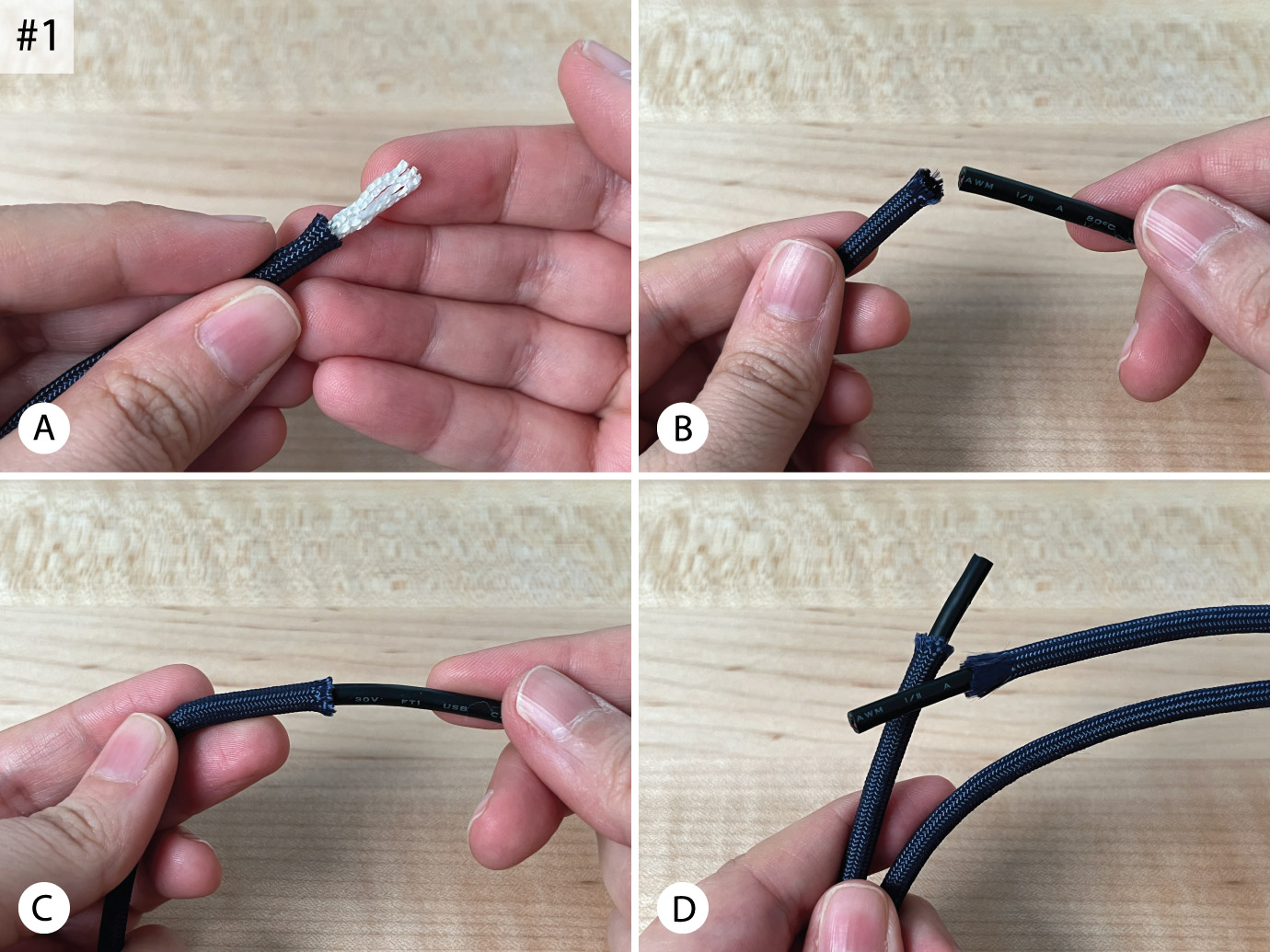
Pull out the white nylon strands inside the paracord [Fig. 1A] and feed the cable wire into the paracord sleeve bit by bit [Fig. 1B–C]. You lose some paracord length as it expands to accommodate the cable, that’s why we cut it a little longer initially.
This process can either go smoothly or frustratingly. There are times when I can easily glide the cable through the paracord I’m using, and there are times when the cable snags on the paracord or the paracord itself is tighter in certain sections than others and more challenging to feed the cable through.
When the cable is eventually fed through completely, make sure you have some cable poking out on each end that’s not covered by paracord, I usually give myself about an inch on each side. If your paracord was too long, you can cut it back a little to achieve the desired outcome [Fig. 1D].
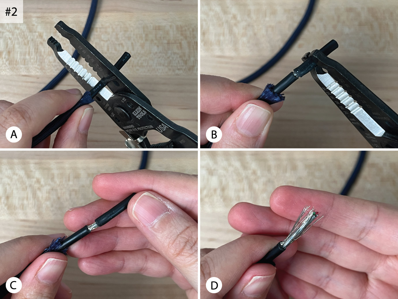
Using the wire strippers, and taking care not to slice too deeply, cut into the cable’s insulation just enough to separate it and carefully pull it off. This will reveal the cable’s inner core [Fig. 2A–D].
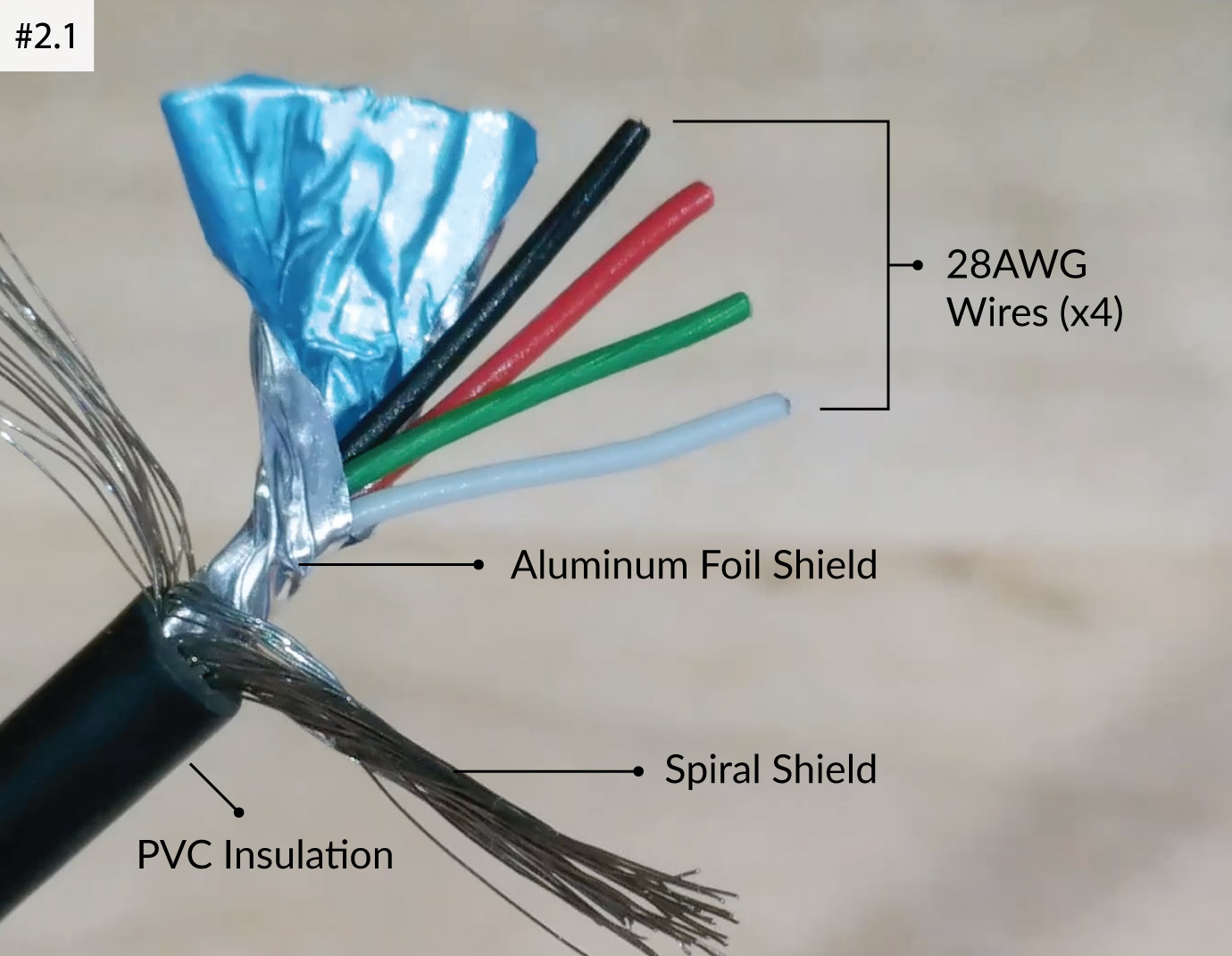
The cable I use has two layers of shielding protecting the four individual wires within: a layer of tin-plated copper wire mesh surrounding an aluminum foil wrapping. Depending on where you purchase your cable, yours might only have the aluminum foil shielding (or none at all). If so, simply ignore any steps that don’t apply to the cable you have.
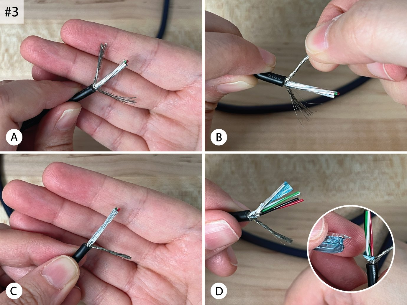
Proceed by twisting the outer shield strands together to move them out of the way. You can twist them all together into one thick braid or separate them into two bundles making them thinner and easier to maneuver [Fig. 3A–C].
Some people cut the shield strands off, but they should be kept to act as a grounding component (that’s what Reddit my research told me, so I leave them intact). The aluminum foil shielding, however, can be safely cut off and discarded [Fig. 3D].
From here on out, be prepared, things get finicky and errors are prone to be made when working with things this small. Be patient. You may have to do over certain steps—I often do! In fact, here’s a short video I filmed last year that shows me doing just that. I’ve started each cable I’ve put together aiming for perfection, knowing I won’t get there, and each has presented challenges and provided opportunities to learn and build on my skills.
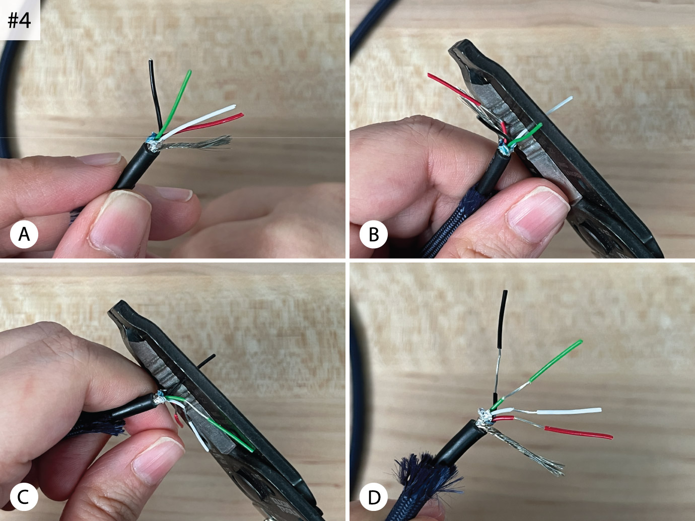
Okay, back to the cable. The next step is to strip the ends of the four individual wires. I tend to give myself a lot of room to work with, so I position the wire stripper a few millimetres from the base of each wire and only partially pull away its insulation. I do this to keep each wire’s strands held together, making things easier and cleaner to work with in later steps [Fig. 4A–D]. I then repeat this process on the opposite end of the cable.
Next, it’s best to tin (cover with solder) the wires we’ve just exposed. Each insulated coloured wire is made up of a bunch of super thin copper strands, and the solder binds them together making them behave as one.
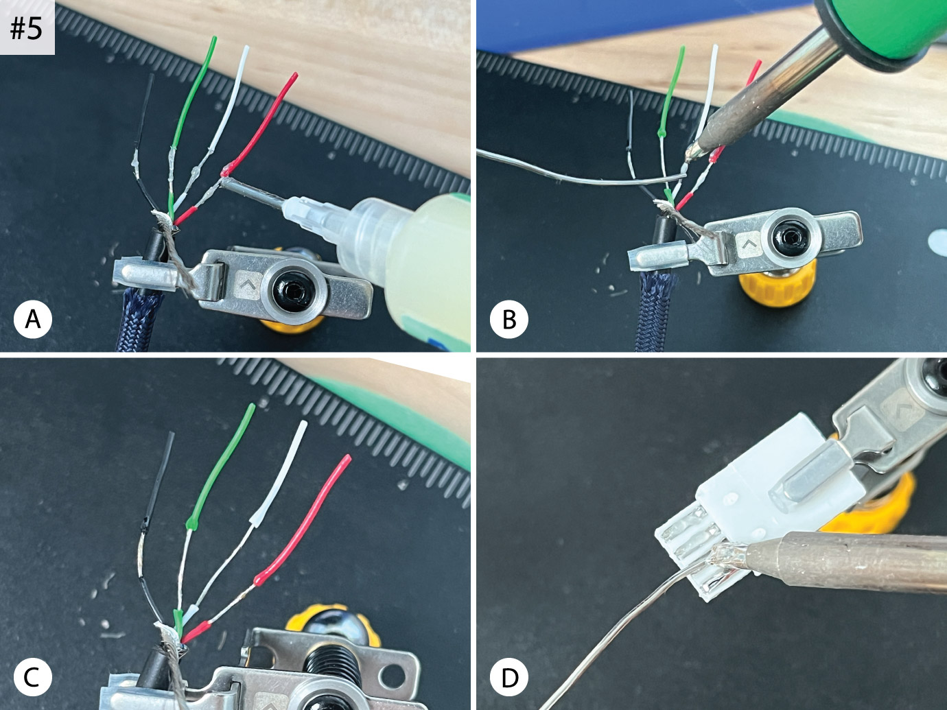
Using the helping hands, clamp the cable and make sure the wires are spread out evenly. Apply solder flux on each wire to help keep the solder flowing [Fig. 5A]. Then heat up each wire one by one with the soldering iron and feed in some solder to coat it [Fig. 5B-C].
I then do the same thing to the USB-A connector. Use another helping hand/clamp to hold the connector with the concave terminals facing you, and once again apply flux and solder to each of its four terminals where the wires will be placed [Fig. 5D]. You can also see these steps illustrated more clearly in the video I shared above.

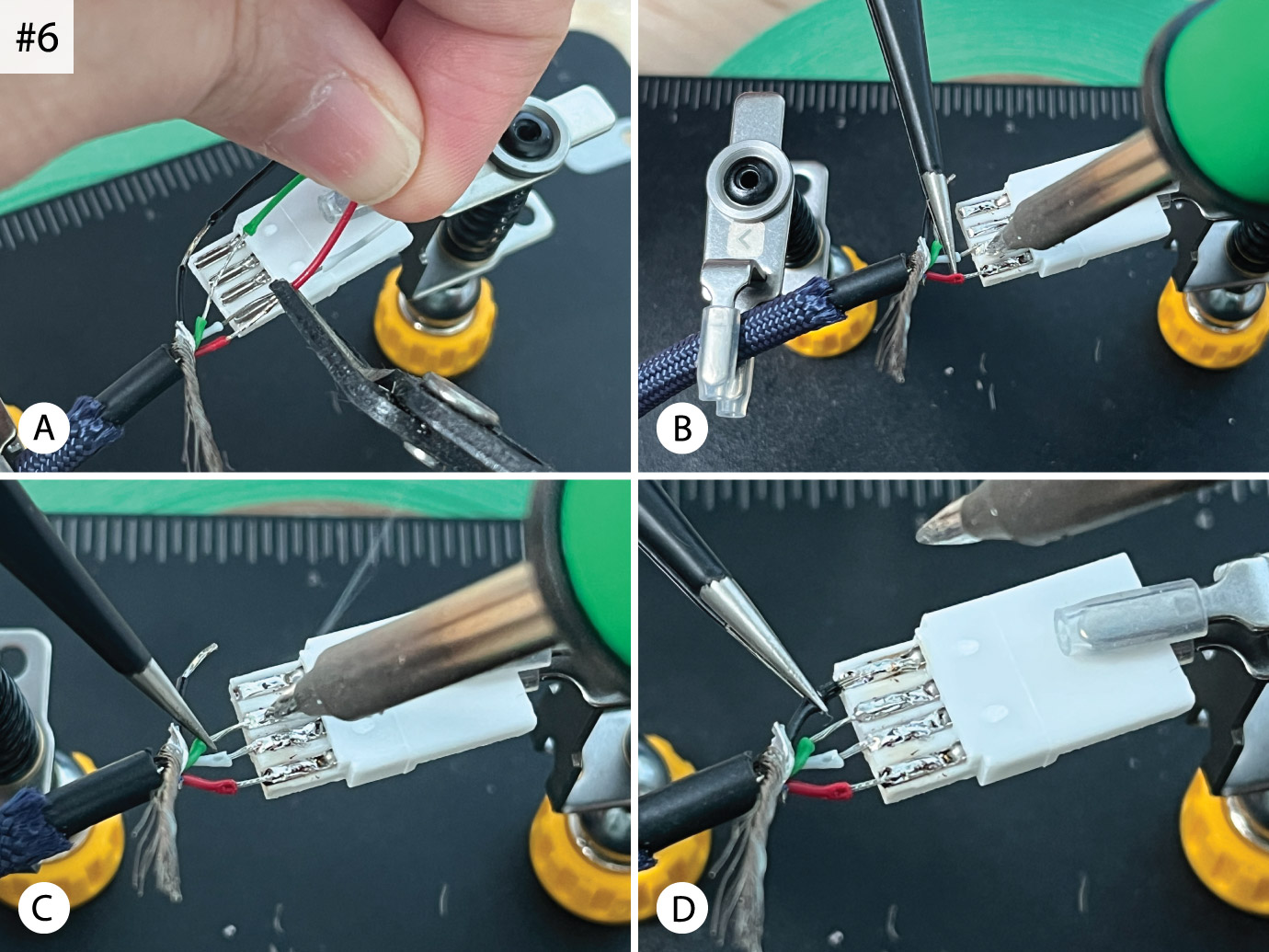
With the USB-A connector terminals pre-soldered, position the cable as close to the connector as you can. Estimate how much length of wire you need to securely fit each wire into its destination slot and cut off the excess wire [Fig. 6A].
Following the USB-A 1.0 and 2.0 universal standard, the order in which the wires are attached is: black for ground (GND) on the far left, followed first by the green wire (D+) then the white wire for data transfer (D-). Lastly, on the far right goes the red wire for power supply (+5v VCC).
I’ve seen some people online reverse the order of the green and white wires…the cable might still work, but it would technically be incorrect, so be sure to follow the diagram I’ve shown here instead. If your cable has different wire colours, I suggest you do some research before proceeding.
Using fine-point tweezers, hold the first wire in place above its spot, then apply heat with the iron to the solder present in the terminal just long enough to melt it and place the wire into it. Remove the iron and keep holding the wire in place for a second or two until the solder solidifies again, encasing the wire within [Fig. 6B–D]. Repeat for each wire. It doesn’t matter which wire you start with, I tend to do the red wire first and work my way to black, but there’s no right or wrong way of doing this.
Yay! The hard part of soldering on the USB-A connector is now done!
To offer the wires some protection, I place a strip of painter’s tape around them [Fig. 7A–B]. It’s mainly to ensure that the wires don’t wiggle around after assembly and to prevent any exposed parts from coming into contact and causing an electric short—ideally, there shouldn’t be any uninsulated visible wire, but I have yet to perfect my technique and my results are often inconsistent. Some people dab some hot glue on the wires instead, but I’m too lazy to bother with a hot glue gun so haven’t yet tried that option.
Then, keeping the side of the connector we were working on facing towards you, slide the connector into the larger piece of its housing [Fig. 7B–C]. Make sure to push it all the way in so that the white plastic of the connector isn’t visible at the bottom and the top edge of it is flush with the opening at the top of the housing [Fig. 7D].
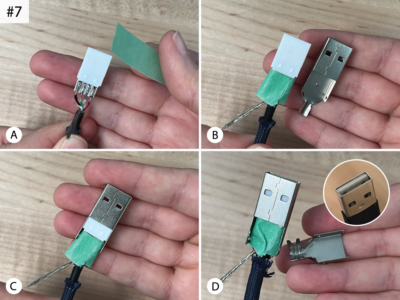
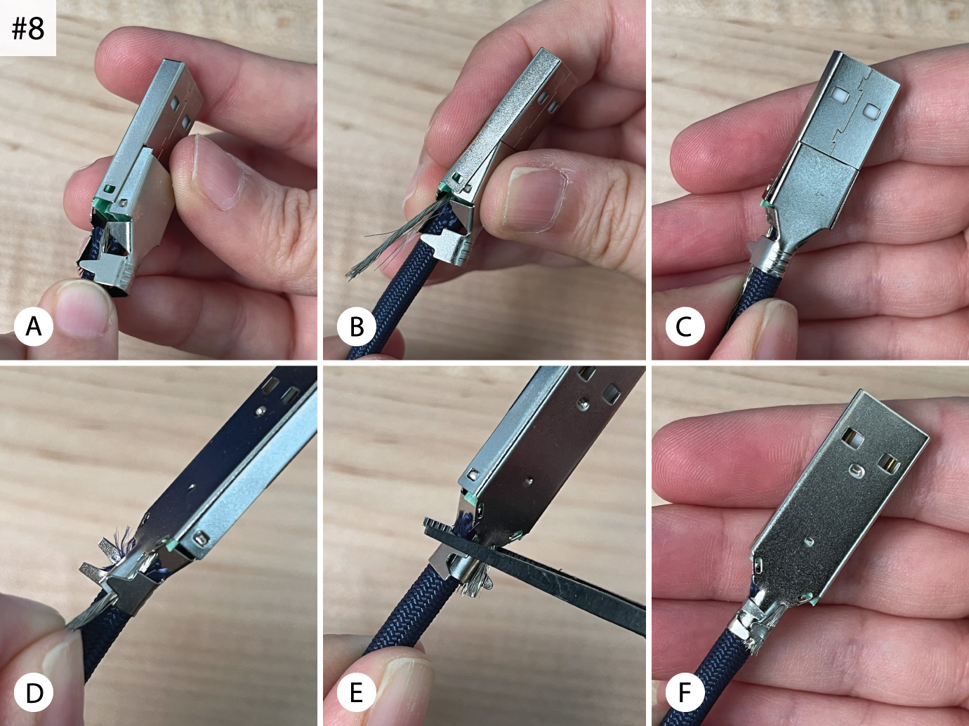
Grabbing the smaller housing cover with the protruding wings [Fig. 7D], position it over the bottom part of the connector that’s still visible [Fig. 8A]. There are little bumps and tabs on the sides of the bottom cover piece that correspond with windows in the larger one. Tuck the shield wire in, keeping it down close to the cable and inside the wings below, then line things up and click the cover down into place [Fig. 8B–C].
At this point, you can trim the shield wire to length while it’s still trapped within the open wings of the cover [Fig. 8D]. Using pliers, cinch closed the metal wings at the bottom [Fig. 8E]. I like to think of the wings coming together like comforting arms, to give everything a tight cozy hug [Fig. 8F].
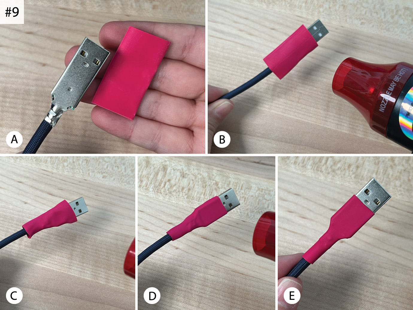
The final step left for the USB-A side of the cable is to apply protective heat shrink tubing for a finished look. Heat shrink comes in different sizes and shrink ratios. For the USB-A side, we’re using 1/2″ 3:1 heat shrink (that means the tubing size is 1/2″ in diameter and shrinks down to a third of its size).
Place a 1.5″ long piece of that heat shrink over the connector [Fig. 9A] and start applying heat, holding the heat gun about 4″ away [Fig. 9B]. Before it shrinks too much, you can make slight adjustments to the tubing’s placement (it tends to slide around a bit at first) to keep it where you’d like. Slowly turn the cable over as you apply heat and keep the heat gun steadily moving over the area until the heat shrink tube is nice and snug [Fig. 9C–E].
Congrats—one side of the cable is now completed!
This side of the cable is often referred to as the “host” side, because it connects to the computer which powers it. The USB-C side we’ll be working on next is often referred to as the “device” side because it plugs into the keyboard. For custom mechanical keyboard cables, host side connectors are traditionally USB-A, and device side connectors are usually USB-C because keyboard PCBs are nowadays commonly designed/equipped with USB-C receptacles to plug into.
Much of what comes next for assembling the USB-C end is similar to what we’ve done so far.
Since the core wires were already stripped when we prepared both sides of the cable earlier, we start with the pre-tinning process by adding flux then adding heat and solder to them. Check [Fig. 5A–C] for reference.
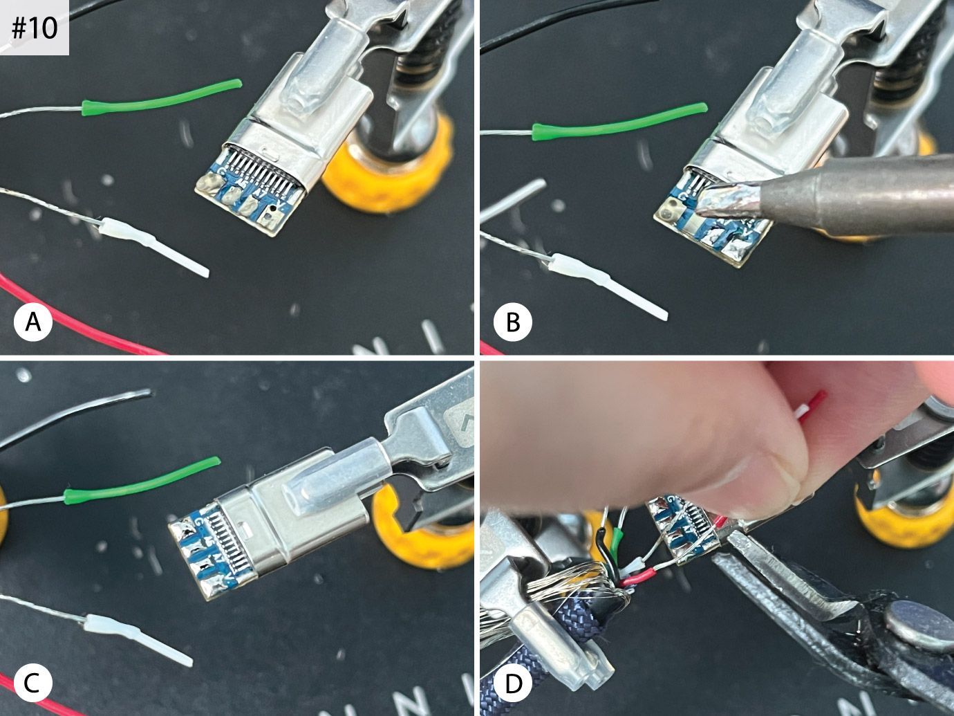
Then we prepare the USB-C connector pads as we did the USB-A connector terminals. Apply a blob of flux [Fig. 10A] to each pad, followed by adding solder [Fig. 10B–C], which I usually do with a pre-tinned iron tip. Pre-tinning the pads makes the often troublesome and awkward process of soldering on the wires a bit easier. Again, you can see this process more clearly in the video I shared above.
With the helping hands, bring the cable wires and connector as close to each other as possible, and just as we did previously, measure how much exposed wire is needed for each colour to reach and fit on its corresponding pad and cut off the excess [Fig. 10D].

For the USB-C connections, follow the same colour order as we did before. One by one, hold each wire above its pre-soldered pad with the fine-point tweezers and apply heat with the iron to the solder just long enough to melt it and place the wire into it. As before, remove the iron and keep the wire in place for a second or two until the solder solidifies and the wire is held firmly in place [Fig. 11A–D].
And there you have it, a soldered USB-C connector!
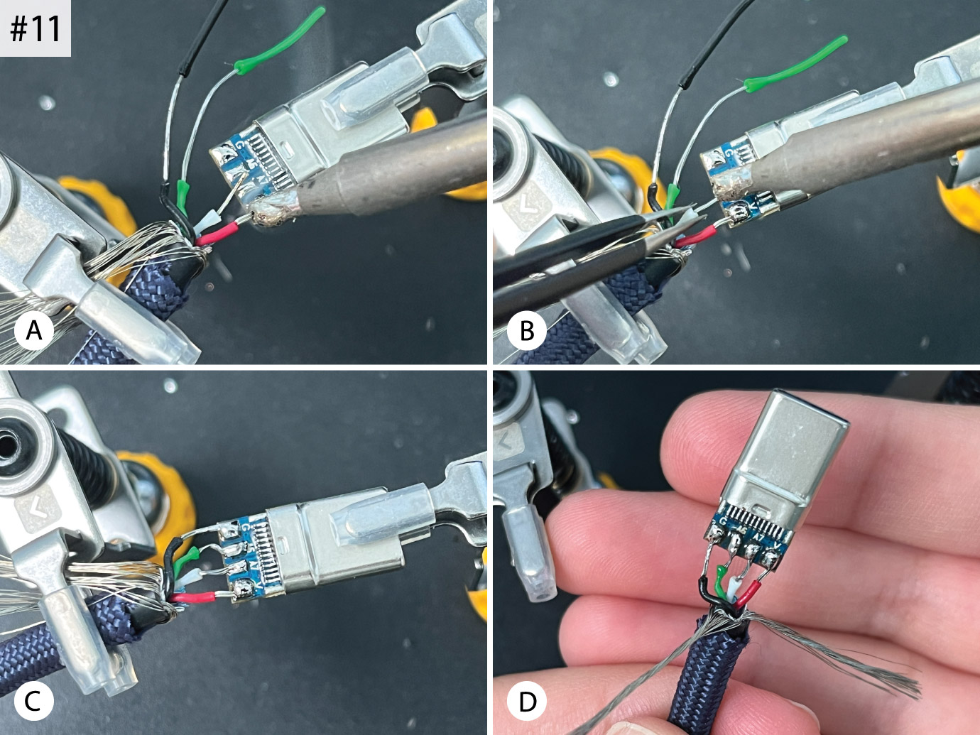
Looking at my work here, it’s not very good. First, I actually had to fix the green wire. You can see that it was a bit too long and had a kink [Fig. 11C], so I removed and snipped off a bit of it to make it straighter [Fig. 11D]. Every time I make a cable, I aim to do a better job with my soldering and wire prep…I can’t seem to get their lengths just right, and see too much exposed wire (the insulation melts away when the wires heat up). Also, the connector itself isn’t centred perfectly with the cable, but these observations just remind me to try to do better next time. In my defence though, my camera setup was in the way to capture this process and I couldn’t see or reach what I was doing as well as I normally would.
If your results look similar to mine, don’t sweat it. You’ll still end up with a working cable as long as you make sure no two wires are at risk of coming into contact with one another. You could even wrap very thin pieces of tape around one or two individual wires if you’re concerned. Just as importantly, make sure that you also don’t have any solder bridges…you should have four separate solder “blobs”, one for each pad/wire, otherwise you’ll have an electric short.
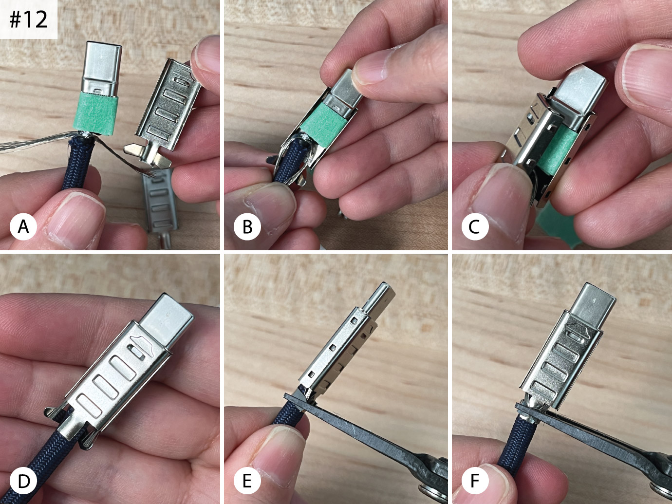
Anyway, you can now add the tape around the wires [Fig. 12A] and proceed with putting on the connector cover. For this side of the cable I had shaped the shielding wire into two separate braids (note to self: this is the better way to do it, remember this for future cables). Starting with the cover piece that has the wings at the bottom, place it behind the connector and hold the two shield braids down towards the cable, keeping them tucked inside the open wings [Fig. 12B]. Bring the other cover piece over, and while sandwiching the connector between the two halves, click it into place [Fig. 12C]. Trim the two shield braids so they’re not poking out too much below the wings [Fig. 12D] , then pinch the wings closed around the cable with the pliers [Fig. 12E–F].
Finally, apply heat shrink to this side as was done on the other (not pictured).
And our work here is done! Woohoo!
Cable-Making Resources
Below is the short list of stores that I’ve personally purchased my cable supplies from, except for the heat shrink, which I had purchased previously from a small custom cable business that no longer exists. When I do purchase heat shrink tubing in the future, I’ll probably be using WireCare.
I started with cable kits, and recommend doing so if you’ve never put one together before, for the convenience of one-stop shopping and not worrying about gathering supplies. Eventually, as I kept practicing and making more cables, I wanted a bit more freedom with quantities and supplies, so I started to buy components from various sources/sellers.
Cable Kits and Parts: MechCables | MinoKeys
Cable: QianFang Store (AliExpress)
Paracord: Canada Paracord
USB Connectors: GT NinthQua Store (AliExpress) USB-A 2.0 | USB-C 2.0
I didn’t think that reading about the creation of a usb cable could make me so delighted! You are a true wonder Fin ✨❤️